Oshima Shipyard
Oshima Shipyard is a factory that can efficiently
build bulk carriers of 30,000 to 100,000tons
Factory features
Independently distributed factory location
Factory buildings are arranged in a line which follows the production process. Each process is completed in each factory building, and the processed steel plates and blocks are transported to the stock area. This stock area serves as a buffer for process adjustment. In the buildings for block assembly, blocks are categorized and workers can do their job at fixed position using work cart on the production line, and it is designed to make work arrangements done efficiently.
Stock area
The simultaneous construction of four vessels at the dock, a feature of Oshima Shipyard, is a construction method that can be realized only with our huge stock area. Blocks are assembled for each vessel, but in the construction stage, two units are constructed in parallel. Therefore, a space is required between the assembly and the construction stage where blocks for up to two ships can be stocked. And we have a stock space that satisfies it.
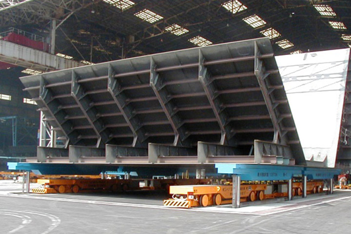
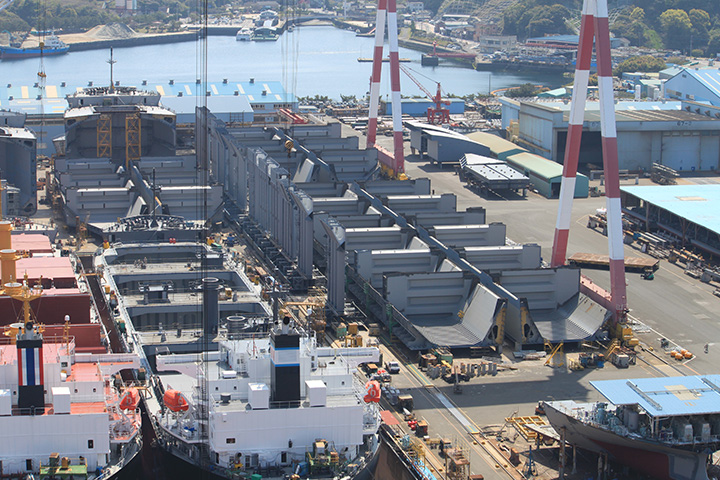
Grand assembly site
At the construction stage which is a final production process, we connect smaller blocks into a large block at grand assembly site. By doing this, it is possible to shorten the construction period in the dock. We have enough grand assembly space to construct blocks equivalent to two ships in parallel. We can build comparable grand assembly blocks for 30,000 to 100,000 tons bulk carrier and install them under same schedule, as we have two 1,200 tons goliath cranes in the dock.
Introduction of Oshima Shipyard
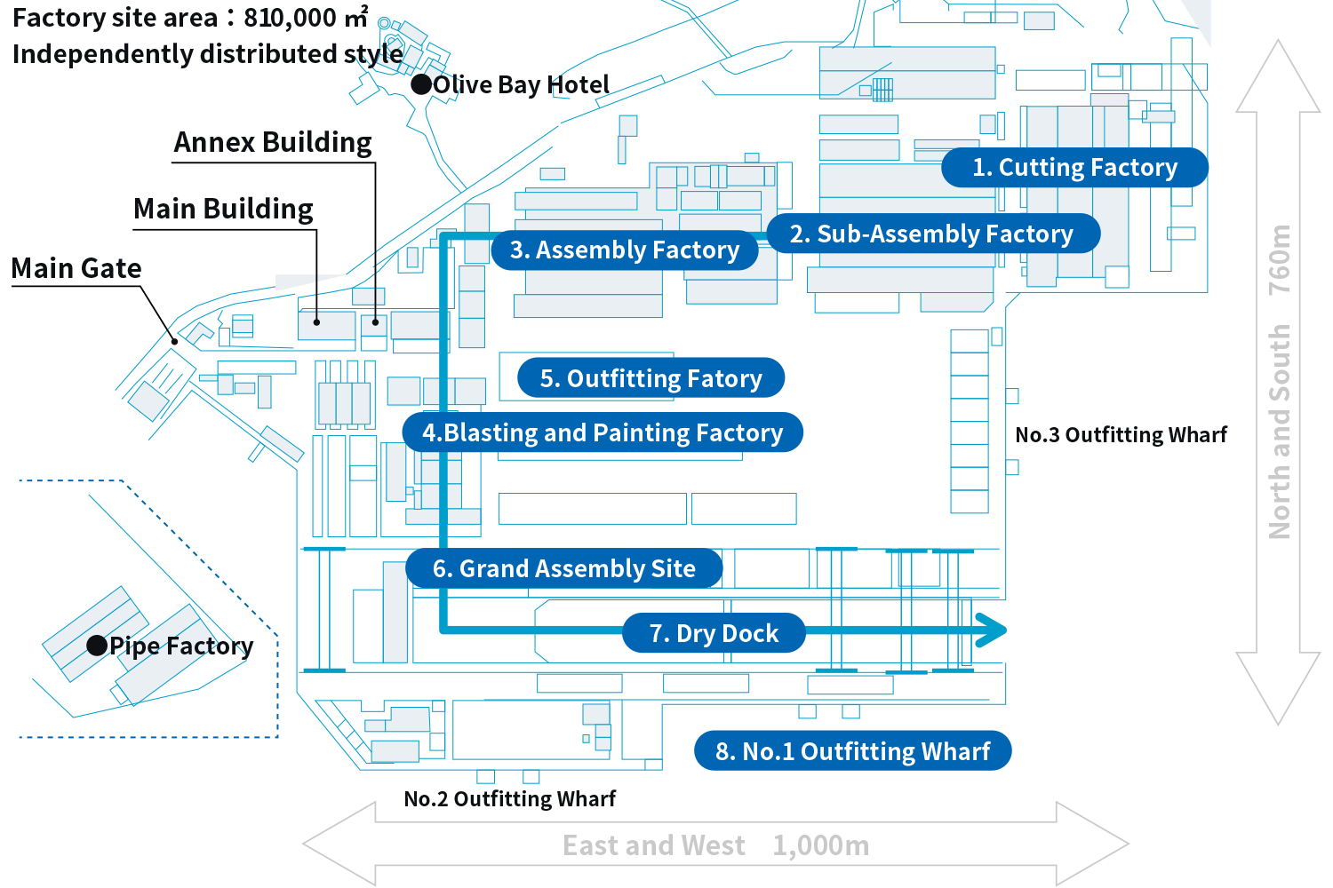
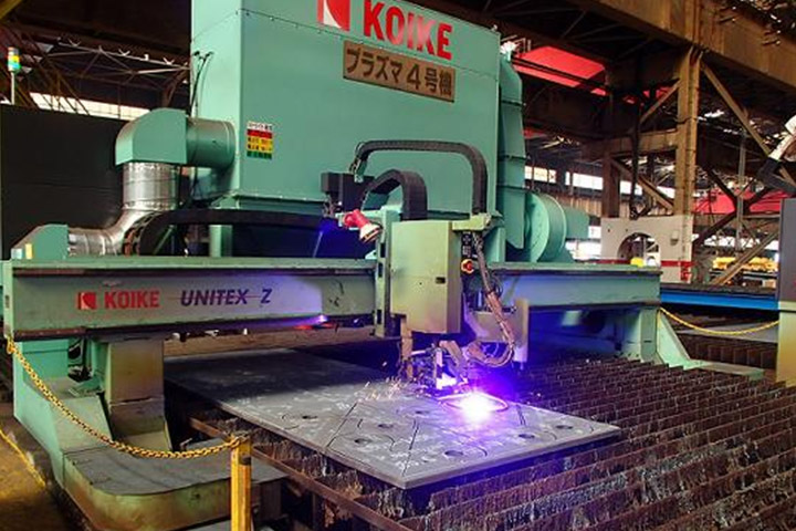
1. Cutting factory
Unloaded steel plates and profiles are cut into parts here. The maximum size of steel plate is 22.5m in length and 4.5m in width. Steel plates are cut with a NC plasma or laser cutting machines. Each ship has about 50,000 parts.
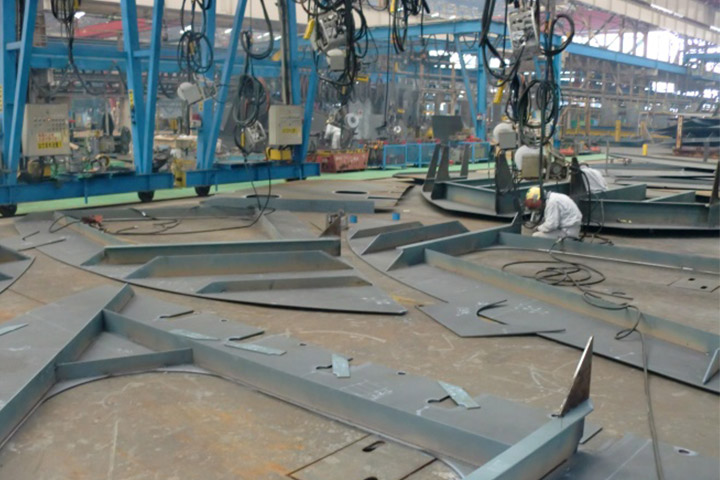
2. Sub-assembly line
At sub-assembly line, small and middle sized blocks are assembled by combining cut parts. The blocks are categorized and assembled on a designated assembly line. The manufactured blocks are transported to the next process by carrier. In addition to block assembly, we also work on bending plates by press machines and burners.
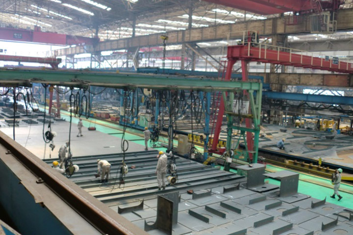
3. Assembly line
At Assembly line, small and middle sized blocks are connected and large sized blocks are built. The blocks are categorized as in the sub assembly line and each line manufactures blocks with similar shapes. Bogie conveyors are use in this line, so large blocks are built on straight line. The largest block may weigh more than 400 tons. The blocks are transported by carriers to the next process.
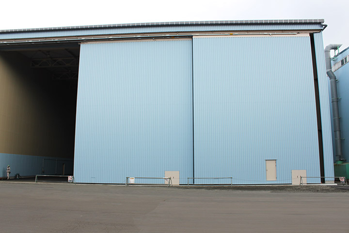
4. Blasting and painting factory
At blasting and painting factory, blocks are blasted and painted. Blasting is the work of spraying small iron powders called grit by compressed air to clean the plate surface. Because control of temperature and humidity is important in painting, painting factory building has sliding doors and dehumidifiers.
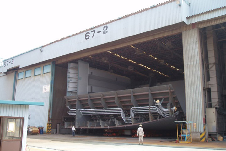
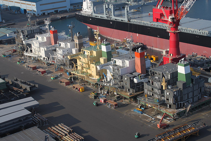
5. Outfitting factory
At outfitting factory, pipes and electric cable are installed to blocks such as engine room. We carry in blocks and install pipes and cable in advance where possible. Some blocks are inverted to improve posture at work.
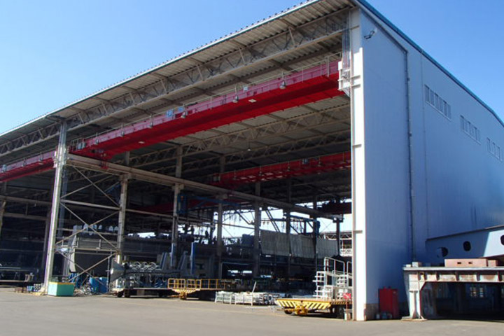
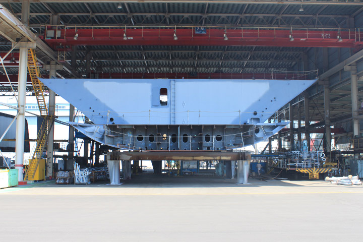
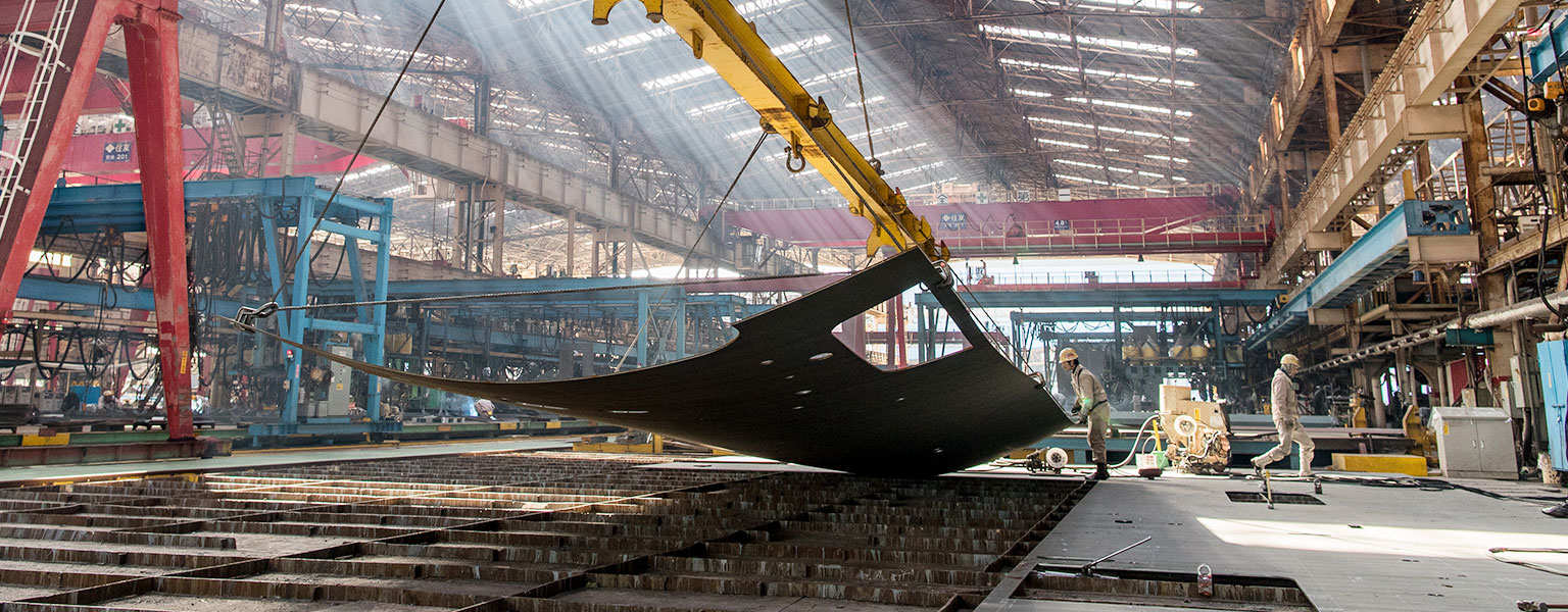
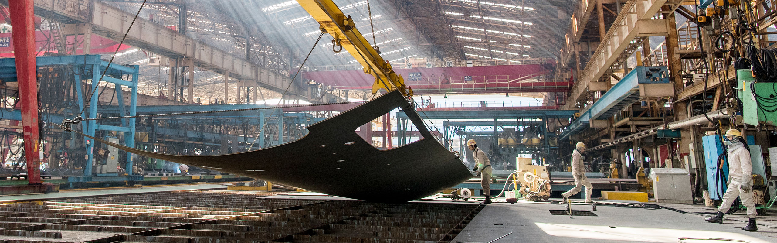
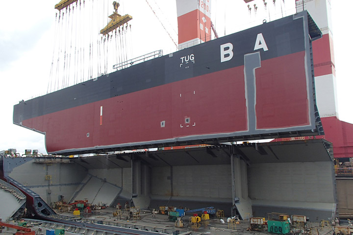
6. Grand assembly site
This is the place where the grand assembly blocks are built by connecting large blocks from assembly line. There are two 1,200 tons and 350 tons Goliath cranes in this site. Two sets of Goliath cranes are used to hoist the grand assembly block into the dock. The maximum weight of grand assembly block can be about 2,000 tons.
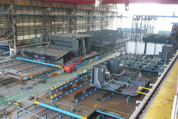
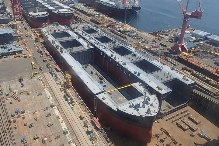
7. Dry dock
The dry dock is where the hulls are constructed from grand assembly blocks and launched. The dock is 535m long, 80m wide and 13m deep. We construct four ships, a set of 2 ships is built in parallel, and another set is placed longitudinally for simultaneous construction. Two ships in a set launch at the same time.
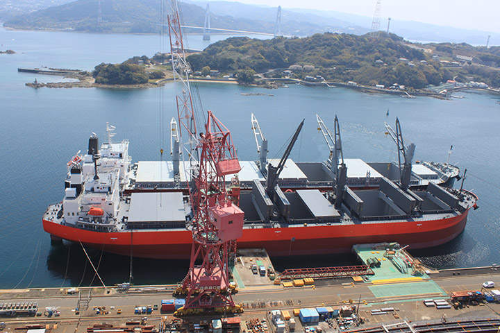
8. Outfitting wharf
At outfitting wharf, the equipment on launched ship is operationally adjusted and the final painting of the deck is done. After the adjustment of the equipment, a sea trial is performed to confirm that the equipment operates as designed and satisfies performance in the specification. After completion, a naming ceremony is held at No.1 Wharf and delivered to the ship owner.
Advantages of Software Modelling
A ship being a large and complex structure, it cannot be constructed in a trial and error method.
The design department uses 3D-CAD so the ships can be built efficiently on site.
Initial Design Stage
A 3D model of the hull is generated during the initial design stage, and initial scantling check and the structural arrangement, extraction of 2D CAD for drafting of Key Plans, and estimation of hull weight are carried out. This 3D model is converted to an FEM model which is used for Structural Strength analysis thereafter. By carrying out an FEM analysis and followed by a simulation on 3D model it is ensured that the designed structure is safe enough to withstand the assumed navigational conditions that ships will encounter over the course of their lifetime and applying the most severe and stringent strength conditions.
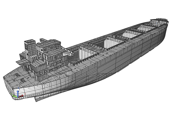
3D model of hull
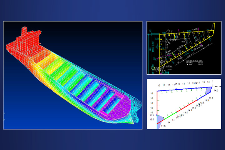
Strength analysis example
Detailed Design Stage
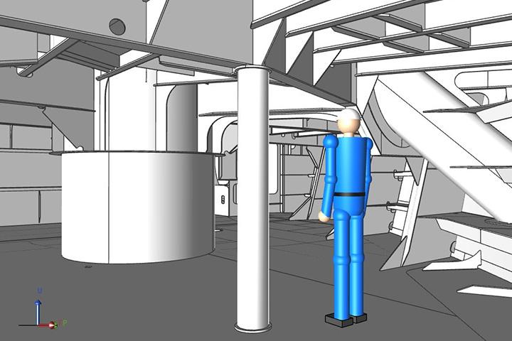
Verification with actual equipment and part data
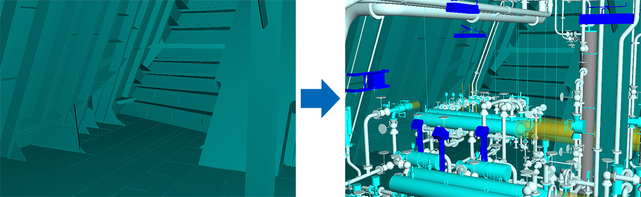
All the Structural elements required in the production site are also 3D modelled. This is an important task for the design and yard staff to identify the problems in advance well before the construction, and to achieve an efficient production considering the construction equipment and scenarios in the production site.
In the engine room, various equipment that becomes the heart of the ship are arranged, such as the main engine for the propulsion, the generator for electricity, and the numerous pumps. 3D CAD modelling is utilized to design these equipment and complex detailed piping such as fuel transfer line and cooling water line.